Post Stastics
- This post has 1977 words.
- Estimated read time is 9.41 minute(s).
Introduction
RS-232, often referred to as a legacy serial communication standard, has been the backbone of communication in electronics and computer systems for decades. Developed in the early 1960s, RS-232 became the standard for robust, reliable data transfer between computers, modems, and peripherals. While USB, TTL serial, and wireless protocols have supplanted RS-232 in consumer electronics, it continues to play a vital role in certain industrial, embedded, and legacy systems.
This article aims to clarify the technical aspects of RS-232, debunk common misconceptions, and provide a detailed guide to the signals, voltages, and usage. We will also explore how RS-232 has evolved, how TTL serial communication came to prominence, and the effects of new technologies like USB and wireless communication.
A Brief History and Evolution of RS-232
The RS-232 standard was first published by the Electronic Industries Association (EIA) in 1962, initially designed to facilitate communication between telecommunication devices. It evolved through several iterations:
- RS-232A (1969): The first major revision to the RS-232 standard, introducing new specifications for signal voltage levels and connector types.
- RS-232B (1975): This revision introduced guidelines for increased cable lengths and signal timing.
- RS-232C (1987): The most widely adopted version, it reduced voltage levels to ±12V (typical) from RS-232B’s ±15V, improving compatibility with newer hardware.
A common misconception is that RS-232C uses 5V logic levels (like TTL). In reality, it employs bipolar signaling (±3V to ±15V), with ±5V to ±12V being typical.We will discuss this in more detail later.
RS-232 Signals and Connector Pinouts
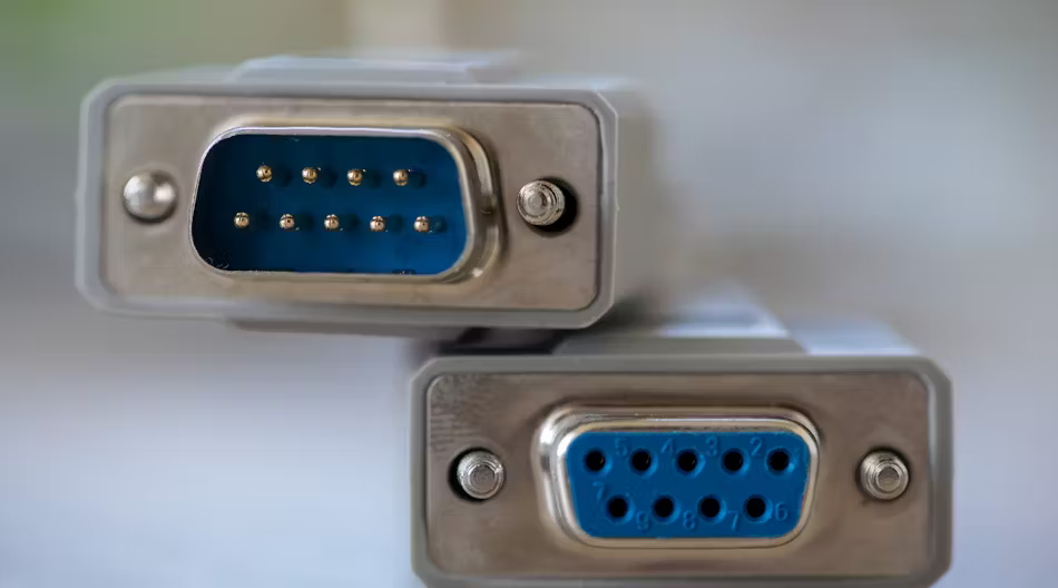
RS-232 utilizes multiple signal types, each with a specific role. The two most commonly used connectors for RS-232 are the DB9 and DB25 connectors. Below, we will explore the various signals in these connectors and their respective pinouts.
DB9 Connector Pinout
The DB9 connector is more common in modern RS-232 applications due to its compact size. Below are the signal assignments for the DB9 connector:
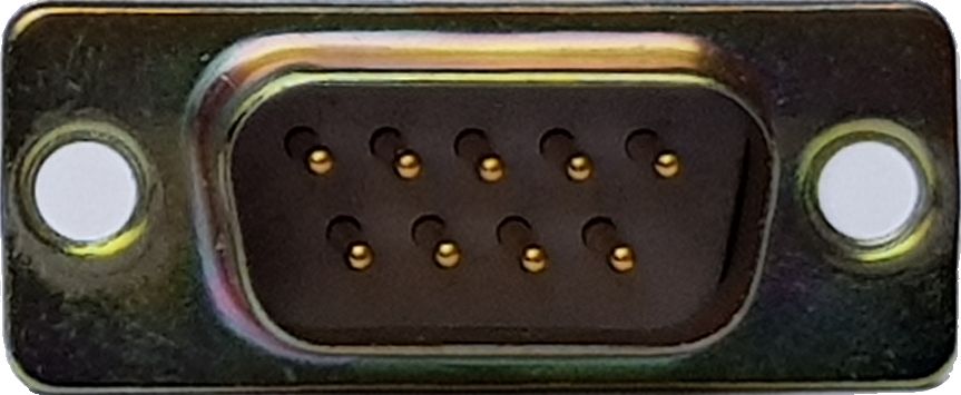
| Pin Number | Signal Name | Description | Direction |
|---|---|---|---|
| 1 | DCD (Data Carrier Detect) | Detects if a modem is connected | Input |
| 2 | RXD (Receive Data) | Receives data from the DTE | Input |
| 3 | TXD (Transmit Data) | Sends data to the DCE | Output |
| 4 | DTR (Data Terminal Ready) | Indicates the DTE is ready | Output |
| 5 | GND (Signal Ground) | Common ground reference | – |
| 6 | DSR (Data Set Ready) | Indicates DCE is ready | Input |
| 7 | RTS (Request to Send) | Request to transmit data | Output |
| 8 | CTS (Clear to Send) | Indicates DCE is ready for data | Input |
| 9 | RI (Ring Indicator) | Indicates incoming call | Input |
DB25 Connector Pinout
The DB25 connector is more versatile and was widely used in older RS-232 systems, especially for modem communication. It contains more signals, including additional handshaking lines.

| Pin Number | Signal Name | Description | Direction |
|---|---|---|---|
| 1 | Protective Ground | Ground for shielded cables | – |
| 2 | TXD (Transmit Data) | Sends data to the DCE | Output |
| 3 | RXD (Receive Data) | Receives data from the DTE | Input |
| 4 | RTS (Request to Send) | Request to transmit data | Output |
| 5 | CTS (Clear to Send) | Indicates DCE is ready for data | Input |
| 6 | DSR (Data Set Ready) | Indicates DCE is ready | Input |
| 7 | GND (Signal Ground) | Common ground reference | – |
| 8 | DCD (Data Carrier Detect) | Detects if modem is connected | Input |
| 9 | +12V | Voltage line for powering devices | Output |
| 20 | DTR (Data Terminal Ready) | Indicates DTE is ready | Output |
Connecting two pieces of equipment together over a RS-232 link requires TX (transmit) line to be coupled to RX (receive) lines in both directions, and a common ground connection between the two devices. Where hardware handshaking is required, “request” lines need to be coupled to “ready” lines in both directions.
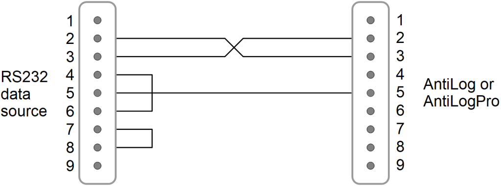
In most cases, a simple 1:1 wired cable can be used for plug to socket connections. However, if both pieces of equipment have the same connector type fitted (e.g. both have male connectors) then the required crossover cable is called a ‘null modem cable’. The following diagram shows a fully specified null modem cable using two 9-pin Sub-D connectors.
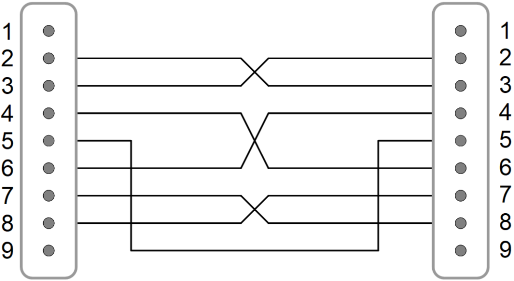
For basic communication without hardware handshaking, a null modem cable requires only three wires: crossed TX/RX lines and a shared ground. Loopback connections (e.g., tying DTR to DSR) can simulate handshaking if needed.
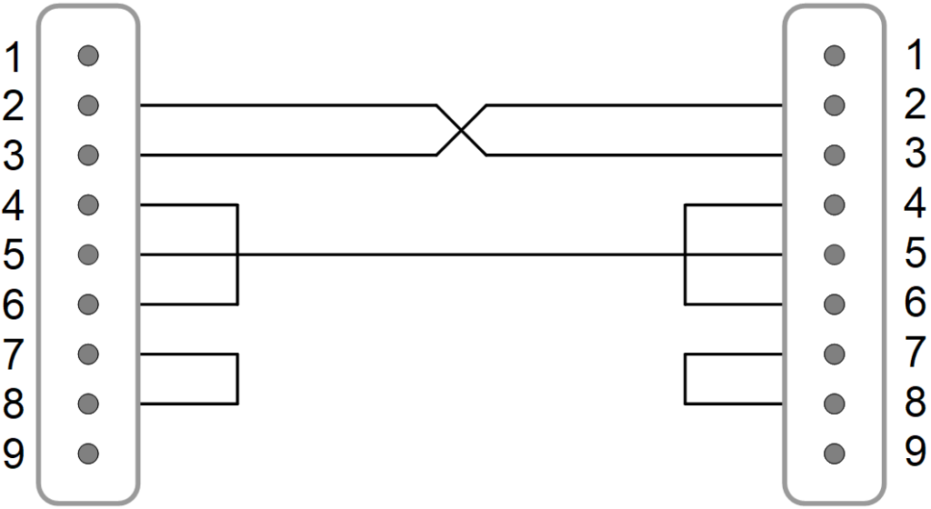
Some equipment may require null modem cables with a basic three-wire interface and loopback connections at the data source end.
RS-232 Signal Characteristics and Voltages
One of the defining characteristics of RS-232 is its voltage levels. RS-232 signals are bi-polar, meaning they alternate between positive and negative voltages to represent binary data (Mark/Space). Here’s a breakdown of the typical voltage levels used in RS-232 communication:
- Logic ‘0’ (Mark): +5V to +15V (typical) | Logic ‘1’ (Space): -5V to -15V (typical)
Thresholds: Valid signals must exceed ±3V, but noise margins improve at higher voltages.
This bi-polar signaling allows RS-232 to resist noise better than TTL or unipolar signaling schemes. The standard defines a voltage range, allowing for flexibility in implementation. The thresholds for valid signals typically start at ±3V, and anything below these values is considered invalid.
Baud Rates and Signal Timings
RS-232 communication is asynchronous, meaning that it does not rely on an external clock signal. Instead, timing is regulated by start, stop, and parity bits. The baud rate refers to the number of signal changes per second. Common baud rates for RS-232 communication include:
- 1200 bps (bits per second)
- 2400 bps
- 9600 bps
- 19200 bps
- 115200 bps (common in modern embedded systems, though RS-232 can technically support higher rates over short distances).

DCE vs. DTE: Gender and Connector Types
Devices using RS-232 are classified as either DTE devices (e.g., computers) typically use male connectors, while DCE devices (e.g., modems) use female connectors.
Connector Gender Convention:
- DTE (e.g., PC): Male connector (pins)
- DCE (e.g., modem): Female connector (sockets)
This ensures proper cross-connection (e.g., TX→RX) when mating devices.”
Flow Control in RS-232
Flow control ensures that data is transmitted at a rate that both sender and receiver can handle. RS-232 utilizes both hardware flow control (RTS/CTS) and software flow control (XON/XOFF). Hardware flow control (RTS/CTS) is preferred for high-speed or noisy environments, as it uses dedicated wires for handshaking. Software flow control (XON/XOFF), though simpler, risks data corruption if control characters appear in the payload.
Common Misconceptions About RS-232 Versions
Many misconceptions about RS-232 stem from confusion between voltage levels in different versions:
- RS-232A: Operated at a maximum of ±25V, allowing for long-distance communication.
- RS-232B: Reduced the maximum voltage to ±15V.
- RS-232C: Further reduced voltages but not to 5V as is commonly thought. It operates between ±12V to ±3V.
TTL Serial vs. RS-232: Why TTL is Not RS-232
While RS-232 uses higher bi-polar voltage levels, TTL serial communication operates between 0V (logic low) and 5V (logic high) or 3.3V in some cases. The simplicity of TTL levels has made it more popular in modern microcontroller-based applications, where RS-232’s higher voltages are unnecessary and harder to integrate.
- Why TTL is Popular: TTL serial interfaces require fewer components and can be directly interfaced with microcontrollers like Arduino, Raspberry Pi, and other embedded systems.
Translating RS-232 to TTL and TTL to RS-232
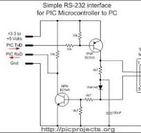
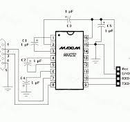
Translating between RS-232 and TTL voltages can be achieved using level shifters. These can be implemented using discrete transistors or specialized ICs like the MAX232. A simple transistor-based circuit can shift the TTL signal levels to RS-232 levels, but for more robust communication, ICs are preferred.
Comparing RS-232, RS-422, and RS-485
Although RS-232 is the most well-known and widely used serial communication standard, it has two important counterparts: RS-422 and RS-485. Each of these standards was designed for specific use cases, and they differ significantly in terms of signaling methods, distance capabilities, noise resistance, and communication modes.
RS-232: Single-Ended Voltage Signaling
RS-232 uses single-ended voltage signaling, meaning that each signal wire transmits data with reference to a common ground. The signal voltages range from +3V to +15V for a logic ‘0’ and -3V to -15V for a logic ‘1’. This single-ended approach limits the effective communication distance to about 50 feet (15 meters) due to susceptibility to noise and signal degradation over long distances. Additionally, RS-232 is designed for point-to-point communication between just two devices, typically one DTE and one DCE.
- Signaling Type: Voltage-based (single-ended)
- Applications: Short-distance, low-speed communication (e.g., PC-to-modem or terminal connections)
RS-422: Differential Voltage Signaling
RS-422 improves upon RS-232 by using differential signaling, which measures the voltage difference between two wires for each signal. This approach significantly reduces noise susceptibility because interference tends to affect both wires equally, allowing the receiver to filter out the noise. RS-422 can operate over much longer distances—up to 4,000 feet (1,200 meters)—and supports higher communication speeds, with a maximum baud rate of 10 Mbps. However, RS-422 is still primarily designed for point-to-point or one-to-many communication (i.e., one transmitter with up to 10 receivers).
- Signaling Type: Differential voltage (voltage difference between two wires)
- Applications: Long-distance communication, industrial automation, and environments with high electromagnetic interference (EMI)
RS-485: Differential Voltage with Multi-Point Capability
RS-485 takes the differential signaling method of RS-422 and adds multi-point communication capability, meaning that multiple devices (up to 32 transmitters and receivers) can share a single bus. Like RS-422, RS-485 uses differential voltage signaling, which makes it highly resistant to noise and ideal for industrial environments. RS-485 can also communicate over long distances (up to 4,000 feet) and supports high speeds of up to 10 Mbps. Its ability to handle half-duplex and full-duplex communication modes makes RS-485 suitable for systems requiring multi-device communication.
- Signaling Type: Differential voltage (supports multi-point bus configuration)
- Applications: Industrial control systems, data acquisition, and applications requiring multi-node networks
Key Differences in Signaling Types
- RS-232: Uses single-ended voltage signaling, making it less resistant to noise and limited to point-to-point communication over short distances.
- RS-422: Uses differential voltage signaling, significantly reducing noise interference and supporting longer distances with faster data rates.
- RS-485: Also uses differential voltage signaling but adds support for multi-point communication, allowing multiple devices to share the same bus while maintaining noise immunity and long-distance capabilities.
Below is the detailed specification comparison table for RS-232, RS-422, and RS-485 based on the requested parameters, including mode of operation, voltage levels, cable lengths, and other important characteristics.
| Specification | RS-232 | RS-422 | RS-485 |
|---|---|---|---|
| Mode of Operation | Single-ended | Differential | Differential |
| Maximum Cable Length | 50 feet (15 m) | 4,000 feet (1,200 m) | 4,000 feet (1,200 m) |
| Maximum Baud Rate | 1 Mbps (short distance) | 10 Mbps (short distance) | 10 Mbps (short distance) |
| Maximum Number of Drivers | 1 | 1 | 32 |
| Maximum Number of Receivers | 1 | 10 | 32 |
| Maximum Driver Output Voltage | ±15V | ±6V | ±12V |
| Minimum Driver Output Voltage | ±3V | ±2V | ±1.5V |
| Driver Output Voltage (Loaded) | ±5V (min) | ±2V (min) | ±1.5V (min) |
| Driver Output Signal (Unloaded) | ±12V to ±15V | ±4V to ±6V | ±4V to ±6V |
| Driver Load Impedance | 3KΩ to 7KΩ | 100Ω to 120Ω | 54Ω to 120Ω |
| Maximum Driver Current | 500mA | 150mA | 250mA |
| Minimum Driver Current | 5mA | 10mA | 10mA |
| Driver Current in Hi-Z State | N/A | N/A | Supported (multi-point bus) |
| Maximum Slew Rate | 30 V/µs | Controlled by driver design | Controlled by driver design |
| Minimum Slew Rate | 4 V/µs | Controlled by driver design | Controlled by driver design |
| Receiver Max Input Voltage Range | ±25V | ±10V | ±12V |
| Receiver Min Input Voltage Range | ±3V | ±200mV | ±200mV |
| Receiver Input Resistance | 3KΩ to 7KΩ | ≥ 4KΩ | ≥ 12KΩ |
| Termination Required | No | Yes (for long distances) | Yes (for multi-point systems) |
| Communication Mode | Full-duplex | Full-duplex | Half-duplex or Full-duplex |
| Noise Immunity | Low | High | High |
| Typical Applications | PCs, Modems, Printers, Teletypes | Industrial Automation, Sensors | Industrial Control Systems, Networks |
Key Notes:
- RS-232 is best for short-distance, low-speed communication between two devices (DTE and DCE), with low noise immunity.
- RS-422 offers differential signaling, which reduces noise susceptibility and supports longer cable lengths with higher baud rates, suitable for point-to-point or one-to-many communication.
- RS-485 adds multi-point capability, allowing for up to 32 drivers and receivers on a single bus, making it ideal for networked, multi-device communication in industrial environments.
- Note: RS-422/485’s differential signaling enables longer distances but requires twisted-pair cables and proper termination for optimal performance.
RS-232’s Place in the Modern World
Despite newer technologies like USB and wireless communication, RS-232 continues to serve critical roles in industrial, embedded, and legacy systems. It’s valued for its simplicity, reliability, and ability to function in noisy environments over short distances.
Conclusion
Despite its age, RS-232 persists in industrial automation, medical devices, and legacy systems due to its noise immunity, simplicity, and deterministic behavior—qualities newer protocols often sacrifice for speed.
Resources
- RS-232 Standard Documentation (EIA)
- RS-232 to TTL Conversion Guide (MAX232 Datasheet)
- Arduino Bit-Banging Serial Communication Tutorial
