- Introduction to Electronics for Hobbyists
- Understanding Resistors: Types, Power Ratings, High Voltage Applications, and Series & Parallel Circuits
- Resistor Basics: A Comprehensive Tutorial with Experiments
- Capacitors: A Comprehensive Guide
- Capacitor Basics: An In-Depth Tutorial with Experiments
- Understanding Inductors: Types, Ratings, Applications, and Selection
Post Stastics
- This post has 1052 words.
- Estimated read time is 5.01 minute(s).
Resistors are fundamental components in electronics, used to limit current, divide voltages, and perform other critical tasks. In this tutorial, we will dive deep into the basics of resistors, covering their behavior, characteristics, and applications. Along the way, we will guide you through a few hands-on experiments to solidify your understanding.
Table of Contents:
- What is a Resistor?
- Resistor Notation: Color Codes
- Ohm’s Law and How Resistors Behave in Circuits
- Types of Resistors
- Experiment 1: Measuring Resistance with a Multimeter
- Experiment 2: Series vs. Parallel Resistors
- Experiment 3: Using Resistors to Limit Current in an LED Circuit
- Materials List and Sources
1. What is a Resistor?
A resistor is a passive electrical component that resists the flow of electric current. It is used in circuits to control the amount of current and to provide a voltage drop. Resistors are characterized by their resistance, which is measured in ohms (Ω). The higher the resistance, the lower the current that will flow through the resistor for a given voltage.
The most common types of resistors are:
- Fixed Resistors: These have a constant resistance value.
- Variable Resistors (Potentiometers): These allow you to adjust their resistance.
- Thermistors: Their resistance changes with temperature.
2. Resistor Notation: Color Codes
Resistors use a color code to indicate their resistance value. The colors are read from left to right, with the first two bands representing significant digits, the third band representing a multiplier, and the fourth (if present) indicating tolerance.
Here’s a breakdown of the resistor color code:
| Color | Digit | Multiplier | Tolerance |
|---|---|---|---|
| Black | 0 | 1 | – |
| Brown | 1 | 10 | ±1% |
| Red | 2 | 100 | ±2% |
| Orange | 3 | 1k (1,000) | – |
| Yellow | 4 | 10k (10,000) | – |
| Green | 5 | 100k | ±0.5% |
| Blue | 6 | 1M (1,000,000) | ±0.25% |
| Violet | 7 | 10M | ±0.1% |
| Gray | 8 | – | ±0.05% |
| White | 9 | – | – |
| Gold | – | 0.1 | ±5% |
| Silver | – | 0.01 | ±10% |
For example, a resistor with the color bands brown, black, red, and gold would have a resistance of 1kΩ with a ±5% tolerance.
3. Ohm’s Law and How Resistors Behave in Circuits
Ohm’s Law defines the relationship between voltage (V), current (I), and resistance (R) in a circuit. It is written as:
$V = I \times R$
This means that the voltage across a resistor is directly proportional to the current flowing through it and the resistance. If you know any two of these quantities, you can calculate the third.
Example Calculation
Suppose you have a 1kΩ resistor and a 9V battery. Using Ohm’s Law:
$I = \frac{V}{R} = \frac{9V}{1000Ω} = 0.009A = 9mA$
This means 9mA of current will flow through the resistor.
4. Types of Resistors
Resistors come in different forms and materials. The most common types are:
- Carbon Film Resistors: Low-cost, with moderate tolerance.
- Metal Film Resistors: Provide better accuracy and lower noise.
- Wirewound Resistors: Made by winding a wire around a ceramic core, they are used for high-power applications.
- Surface Mount Resistors (SMD): Small and compact, used in modern electronics.
- Potentiometers: Variable resistors that allow you to manually adjust the resistance.
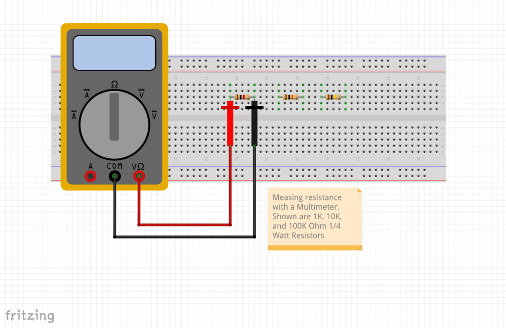
5. Experiment 1: Measuring Resistance with a Multimeter
In this experiment, you’ll learn how to use a multimeter to measure the resistance of different resistors.
Materials:
- A digital multimeter (Harbor Freight offers a low-cost option)
- Several resistors (100Ω, 1kΩ, 10kΩ)
Steps:
- Turn on the multimeter and set it to the resistance (Ω) measurement mode.
- Select the correct range for your multimeter. If you’re unsure, start with the highest range and work your way down.
- Place the probes on each leg of the resistor. The multimeter will display the resistance value.
- Compare the measured value to the resistor’s color code to check for accuracy.
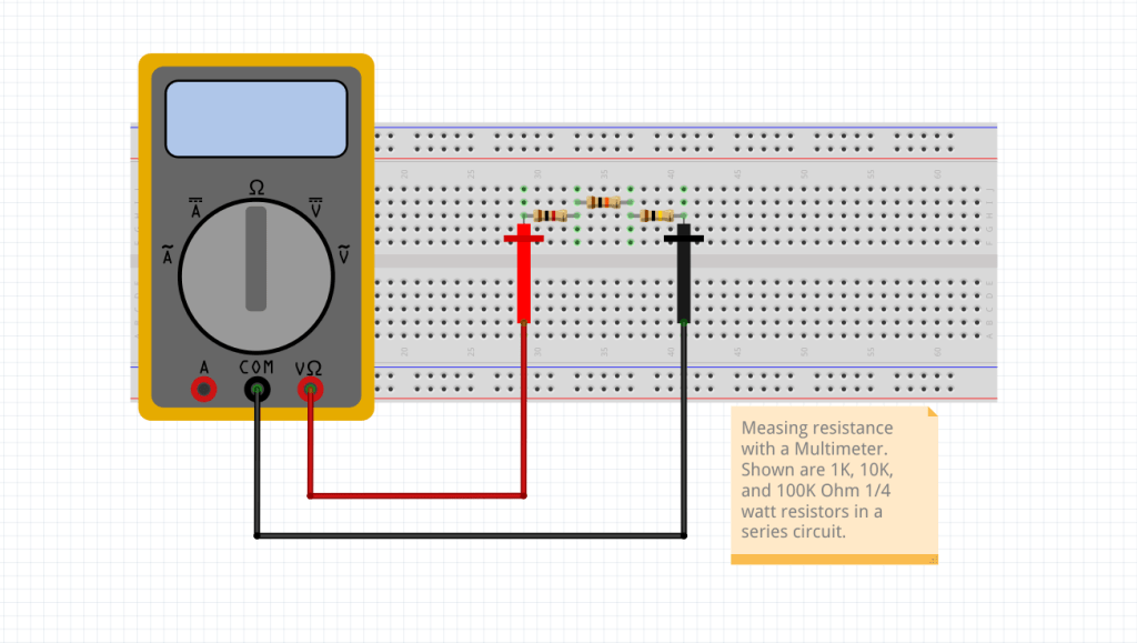
6. Experiment 2: Series vs. Parallel Resistors
In this experiment, we’ll explore how resistors behave when arranged in series and parallel.
Materials:
- Breadboard
- Several resistors (100Ω, 1kΩ, 10kΩ)
- Jumper wires
- Multimeter
Steps:
Series:
- Connect two resistors in series on a breadboard.
- Measure the total resistance across the two resistors. The total resistance of resistors in series is the sum of their individual resistances: $R_{total} = R_1 + R_2 + R_3$ When the parallel resistors are all the same value you can use: $R_{total} = \frac{R_1}{n}$ Where n is the number of resistors in parallel.
Parallel:
- Connect two resistors in parallel on a breadboard.
- Measure the total resistance. The total resistance of resistors in parallel is given by: $\frac{1}{R_{total}} = \frac{1}{R_1} + \frac{1}{R_2}$
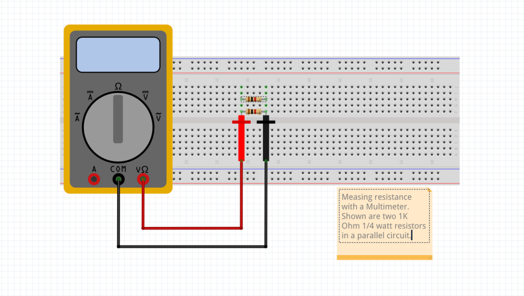
You should observe that the total resistance in parallel is always less than the smallest individual resistor. With the two 1K ohm resistors shown, the measured value should be close to 500 ohm.
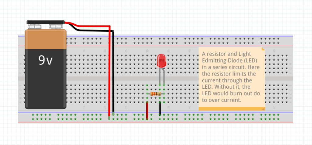
7. Experiment 3: Using Resistors to Limit Current in an LED Circuit
Resistors are often used to limit the current flowing through components like LEDs. In this experiment, we will use a resistor to protect an LED from excessive current.
Materials:
- 1x LED
- 1x 330Ω resistor
- Breadboard
- Jumper wires
- 9V battery and battery clip
- Multimeter
Steps:
- Place the LED on the breadboard. Connect the longer leg (anode) to one end of the resistor and the shorter leg (cathode) to ground.
- Connect the resistor to the positive terminal of the 9V battery using jumper wires.
- When you power the circuit, the LED should light up. The resistor limits the current, protecting the LED from burning out.
- Use the multimeter to measure the current through the circuit and verify it is within safe limits for the LED.
8. Materials List and Sources
Here’s a list of materials you’ll need for these experiments, along with sources for purchasing them:
Resistors:
- 100Ω, 330Ω, 1kΩ, 10kΩ (available from any electronics supplier such as Mouser, Digi-Key, Amazon, eBay, and many more…)
Multimeter:
- Digital multimeter (Harbor Freight offers low-cost options, such as the Cen-Tech 7 Function Digital Multimeter)
Breadboard and Jumper Wires:
Power Supply:
- 9V batteries and battery clips are available at hardware stores or online retailers like Amazon.
LEDs:
- LEDs can be purchased at electronics stores like Mouser or hobbyist websites like SparkFun, Amazon, eBay, etc.
Sources for Components:
- Harbor Freight: Great for affordable multimeters and basic tools.
- Amazon: General supplies for electronics.
- SparkFun: DIY electronics kits and components.
- Adafruit: Makers and hobbyists focused supplies.
- Mouser & Digi-Key: Professional-grade electronics components.
Conclusion
By following these experiments, you’ll gain a solid understanding of resistors and their role in electronic circuits. Each experiment builds on the previous one, helping you progressively understand key concepts such as Ohm’s Law, resistance measurements, and real-world applications.
Next time, we will discuss capacitors. Following that discussion, we will once again post some experiments you can do to gain a better understanding of capacitors.